Monday, July 20, 2009

The Hydraulic Air Compressor - a brief history

The following is an extract from a thesis written by Roy G. Taylor son of Charles H. Taylor and Mabel Morgan. The thesis was submitted in partial fulfillment of the requirements for the degree of Bachelor of Applied Science.

Dept. of Mechanical Engineering,
University of Toronto,
Oct. 31, 1951

Roy is a member of Charles Taylor's second family. He acquired his Engineering degree and worked in the family business with his father Charles H. Taylor Sr. and his older brother Charles (Bud) H. Taylor until they closed down the business. Roy has since retired but has remained both active and creative.

History:

It may be of interest to the reader to know at least a brief history concerning the developmentof this compressor, therefore at this point I will present a review of the major events that led to its first successful application.

One of the earliest forms of compressed air devices had its origin in the early years of the iron age and was known as the trompe or hydraulic air blast for forges. Its purpose was to supply the Catalan forges with a steady blast of air. The preassure produced in this type of compressor were of a very small magnitude being in the neighborhood of one ounce (1 oz.) to one pound per square inch (1 lb./sq. in.) The best type of construction in trompe mechanism was one wherein the range of the apparatus could be produced by means of a sliding gate. The operation of the apparatus may be explained by referring to figure 1. Water falling into the tube draws air through the small inclined holes, indicated by arrows, and carries this air down into the reservoir where the air separates from the water and escapes to the forge. The outlet column is high enough to balance the pressure maintained in the reservoir.


In the year 1877, Mr. J.P. Frizell carried out tests
of a practical scale on this system utilizing a 5 ft. fall and a 36 ft. shaft at the falls of St. Anthony near St. Paul on the Mississippi River. From his tests he proposed a system known as the Frizell system, see figure 2., for which he secured patents. Later compressors were somewhat similar to this system but the actual design involved was quite different in certain respects.


The next major step was made by Mr. C. H. Taylor in 1896 at Magog, Quebec where he erected the first working hydraulic air plant on a practicle scale. The Taylor plant, although essentially utilizing the method outlined by Frizell, was materially different in detail and proportioning of the various parts of the plant. It may be noted here that Mr. Taylor discovered the principle himself by noting how water flowing down the spillway of a dam carried a certain amount of air with it as it plunged under the surface of the river ice. This air carried downstream by the flowing water, released itselt from the water and formed large pockets of air under the ice. This caused the ice to bulge upwards and when he broke one of the pockets and discovered that air under pressure was trapped here he also discovered this principle that he put to much use. Thus independent and ignorant of any other proposed system, he erected at Magog the first plant for the purpose of supplying air to a cotton mill.

The air supply from this plant was ample for the needs of the mill and its success here led to its further application in the field of mining. The efficiency of the plant at Magog though relatively high was improved on by a better proportioning of the parts and the later plants had efficiencies of 82%, an improvement of 20% over the Magog plant. Three separate patents were obtained by Taylor for his design of the hydraulic air compressor in 1896, 1898 and 1900.


Sketches and links


The following links connect to historical sites, Engineering Societies and blog sites that support the engineering and historical significance of Charles Havelock Taylor's design of the Hydraulic Air Compressor.

http://www.cobalt.ca/index.php?option=com_content&view=article&id=49&Itemid=57


Kootenay Plant Sketch:

There appear to be conflicting stories with regard to the Kootenay Air Plant at Ainsworth BC. In the second family account it was said to be rendered inoperable due to the lack of a spur line to the mines and that Taylor had paid back the investors from his own pocket however, I received the following email response from the Kootenay Historical Society;

Dear Mr. Hawkins,
Your message to Nelson was forwarded to us at the Kootenay Lake Archives. However, our internet server is being changed there and so I am replying from my home.
Here is the information that I have found on the Coffee Creek compressor (as we call it) found in "High Grade and Hot Springs - A History of the Ainsworth Camp" by E.L. Affleck 2001.
Page 6: "One of the most interesting early mining plants in the camp was a non-mechanical gravity air compressor, a Taylor air compressor, installed in 1897 on the north canyon wall of Coffee Creek. This device, working on a principle patented by C.H. Taylor of Montreal, compressed air by employing falling water. The plant, using flumed water from Coffee Creek, had a capacity of 5000 cubic feet of free air per minute at 85 pounds per square inch and developed 600 horsepower. The water was dropped vertically down a wood-stave pipe (existing pictures indicate metal pipe, which presumably replaced the initial wood installation) into a vertical shaft about 100 feet deep at the edge of the creek. The air was piped two to three miles to mines as far away as the "United" until about 1910. The "BC Mining Record" of September 1906 carried a detailed description of this plant. One would have anticipated a huge market for this compression device, but it was said that the process leached most of the oxygen out of the air, with the result that the oxygen-starved compressed air piped into underground passages was lethal to workers. This could account for the poor performance of the Taylor Air Compressor in the market." A photograph of the compressor on page 2 is captioned with a statement saying that the compressor collapsed in 1916. See also Page 49.

I hope that this is useful information for you. Sorry not to be able to report that it is still in use or that there are parts of it around.

Sincerely,

Elizabeth Scarlett
Volunteer Archivist
Kootenay Lake Archives
Kootenay Lake Historical Society
Box 537
KASLO, BC V0G 1M0
CANADA
Tel: 250-353-9633
The Archives is open on Monday evenings 7:00 - 9:00 p.m. and Thursday
mornings 9:00 a.m. to Noon except holidays.

Check out our website at www.klhs.bc.ca/archives
<
http://www.klhs.bc.ca/archives>

The statements that "the process leached most of the oxygen out of the air" and "oxygen starved air piped into underground passages was lethal to workers" seems rather far fetched.

It is possible that toxic air was picked up through the leaching of gases within the layers of geological strata and was carried by the compressed air however, this in itself is highly unlikely due to the piping system.

The pneumatic tools used in the mining process do not extract air but rather they exhaust air. The term "oxygen starved" infers that the volume of air exhasted from the tools during each working day was greater than the volume of the mining tunnel. This is also highly unlikely.

A more likely scenario would be the cost in replacing the 1354 foot long wooden stave pipe 4 foot 6 inches in diameter, built against the side of the gorge, as well as the 110 foot high wooden tower was considered too great an expense at the time.

At this point in history it is impossible to evaluate the reasons for shutting down the plant however I must point out that this is the only system both prior to and after construction of the Kootney plant that had this problem. Cobalt produced nearly 10 times horsepower and still operated continuously up until the mid 1980's.

Original Sketches of the Victoria Mine Compressor in Copper Country Michigan


Link to the historic site: http://www.coppercountryexplorer.com/2011/07/the-taylor-compressor/

A special thank you to the anonymous commenter who sent me this fantastic link


1895 to 1914 "continued"

These were the glory years for Charles Taylor not only was he given the honour of building a plant for the great Peterborough Lift Lock but news of his inventive genius had reached Europe.

Charles made many business trips to Europe in the late nineteenth century, and belonged to many of the best social clubs in London and Paris. He saw the Worlds Fair in 1897 at Paris France and was much impressed with the Eiffel Tower and the Hall of Mirrors.

He bought one of Toronto's first cars, a 1911 Ford, at a time when driving was an adventure. A time when gasoline was obtained only in the city center and roads were limited.

In 1901 a Fourth compressor was built in the State of Washington. Then in 1906, a general purpose compressor was constructed in Norwich Connecticut. That same year Taylor was commissioned to build a 550 Horsepower compressor for the Victoria Copper Mine in Rockland Michigan which delivered air at 117 p.s.i. Other plants were built in Tarica, Peru and in Germany.

The largest and most ambitious Air Plant was the Ragged Chutes plant at Cobalt Ontario. Taylor visited Cobalt in 1905 and determined that the conditions and the mining industry were ideally suited to his invention. Work on the plant was completed in 1910.

To finance his company he invited many prominent New York bankers to Cobalt and treated them to a fabulous hunting and fishing expedition that included a huge barbeque of choice moose steaks. Needless to say they were duly impressed with his ability as a host and engineer that he was able to secure their financial backing.


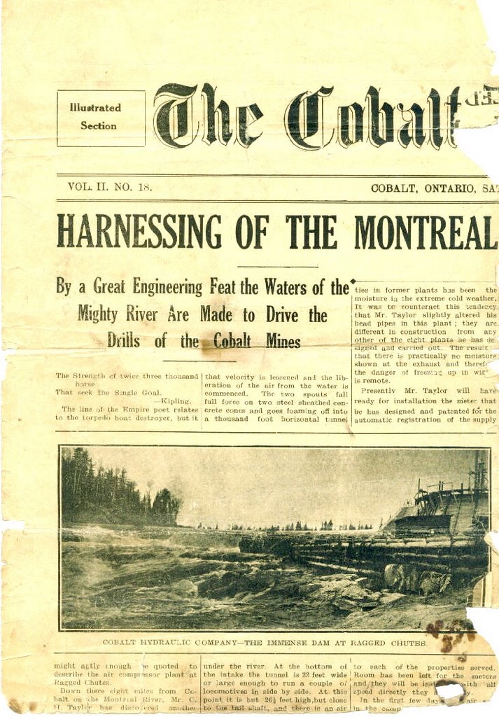
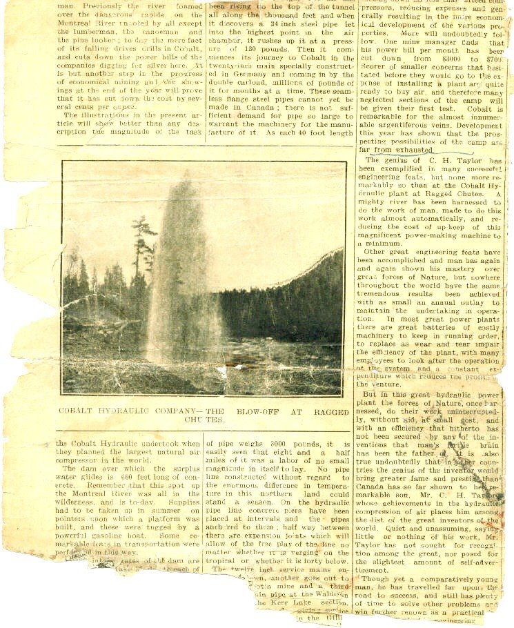
The plant at Ragged Chutes is 5500 H.P. with a 1000 H.P. reserve. A 660 foot weir dam was built across the Montreal River to control the water flow. The air is transported by means of a seamless steel pipe. These specially designed pipes were brought in from Germany. A total of 21 miles of pipe were required for the project.

(More on the Cobalt Plant in the next posting).

1905 - 1910 The building of Ragged Chutes


Ragged Chutes was Charles most ambitious project and his greatest success. The feeder shaft, 351 feet deep and 9 and 1/2 feet in diameter was sunk into the bedrock. The lower 40 feet widens to 11 and 1/2 feet in diameter. At the top of this shaft are twin intake heads each containing 72 intake pipes, 16 inches in diameter.

Water backed up behind the 660 foot wide dam swirls down through these pipes carrying air with it. When the water reaches the bottom of the shaft, it is diverterted into a 1021 foot long horizontal tunnel by a steel sheathed concrete cone.

This tunnel is 20 feet wide and 26 feet high, at the far end a bulge in the ceiling increases the height to 42 feet. The rushing water slows down in this tunnel and the air collects along the roof at approximately 120 p.s.i. A 298 foot tail shaft by 22 feet in diameter returns the water to the surface. Once at the surface it continues down the Montreal River.

The air, under pressure, in the pocket below ground is tapped off by a 24 inch diameter steel pipe and brought to the surface. Here it passes into a valve house and is distributed to the mines of Cobalt.

The air is transported to the mines via a seamless pipe, imported from Germany, specific to this project. There is a total of 21 miles of seamless pipe used for the movement of air to the various mines.

(The photo at the right is of shaft #8 it has a pencil sketch on the back presumably by Charles Taylor that was done on site.)

When more compressed air, than can be used, builds up in the chamber the water level in the tunnel is forced down exposing the end of a 12 inch release pipe. The excess air blows out 10 feet below the surface of the Montreal River resulting in a geyser plume that often reaches 200 feet in the air. It was one of the most impressive site around Cobalt during the hayday of the Air Plant.

To reduce friction and drag in the intake and tail shaft Taylor had to devise a method of drilling in the granite that would ensure a smooth vertical wall. He designed a drilling rig that allowed the men to work from a wooden platform that rotated on a central axis, thus maintaining a constant diameter. Wall fractures in the granite substrate were smoothed with cement to eliminate uneven surfaces.

There were many nay sayers at the time who did not believe Taylors calculations, there were many in the Engineering field that said it could not be done. The general feeling around Cobalt at the time was, "Taylor is crazy, a two bit, so-called engineer, self taught, little better than a mechanic with a bunch of wacky ideas". He was this and more, most visionaries are. The educated and informed doubt the abilities of those without the paper qualification however Taylor not only proved them wrong but his Air Plant was so finely engineered that it operated unabated, but for two maintenance shutdowns, up until fire destroyed it in the 1980's.

( special thanks for the text, in part, to Richard Hillary grandson of CH Taylor).

All That Remains Today


Many Thanks to Jordan Tanner and his friends at Ontario Hydro for these pictures

1905 to 1910 The mines of Cobalt


1905 to 1910 Mining in Cobalt


Silver Sidewalk Lawson Mine
As I mentioned early Charles Taylor was an avid amateur photographer who, during his travels, recorded the history of his time. While being an amateur at the art Charles excelled in his knowledge of the camera and its limited ability.

Many of these photo's are not only rare in their subject matter but they are rare in their technical sense as well.


Surface vein at the Lawson Mine

Surface Vein


Drilling at La Rose Mine


Mucking at La Rose

Underground Vein at La Rose


La Rose Vein